Avian-friendly wind power
Part 1 of 2
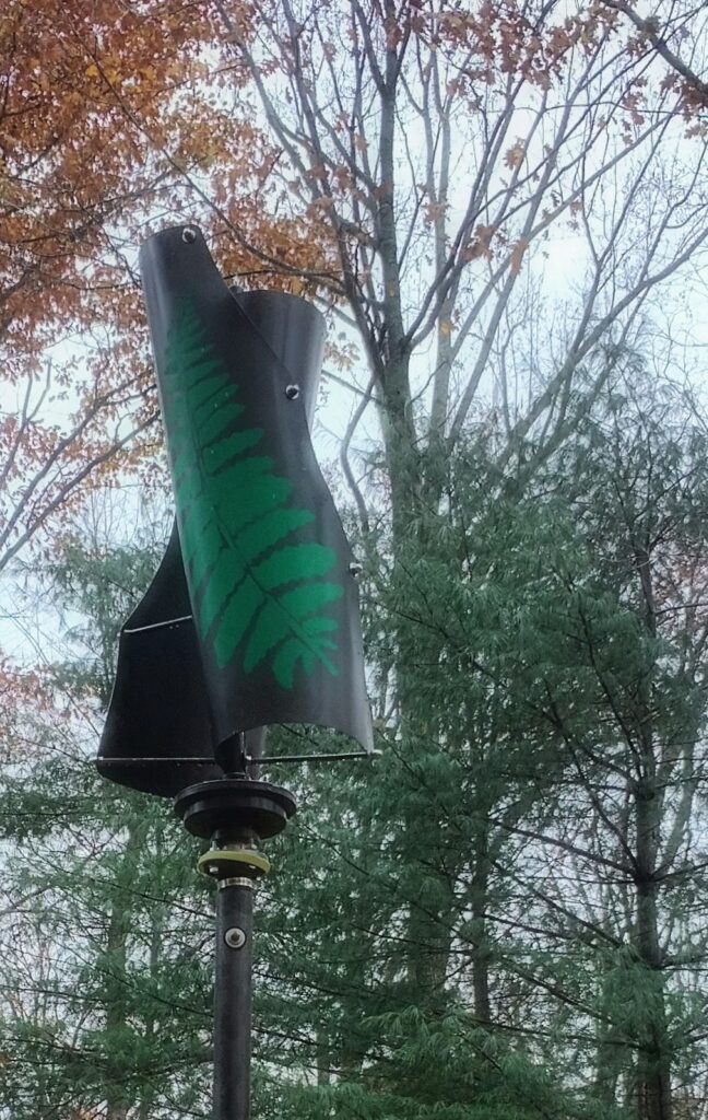
Everybody is asking, ”What is it?” So, I tell them, “It’s a magnetic levitation vertical helix wind power generator with a 400 watt rating made by Maglev”. It came with a 12/24 volt charge controller, nuts, bolts, a mounting disc (which I did not use), a single instruction sheet (one side in English) on how to attach the blades to the generator, and nothing – I mean nothing – about how to install or mount it and wire it to a 12/24 volt battery bank.
It’s been a journey. At the School of Mines, I was a mechanical engineering student, not electrical, so the learning curve was steep. I procrastinated with artistic immersion, deciding to paint the glossy white blades and chrome axis a deep forest brown with a matte finish. I drew a template of a fern leaf resembling the big Goldie’s wood ferns that adorn the forest here in South-central Indiana, then made a stencil and spray-painted a big green fern on each of the double helix blades. Let the research begin!
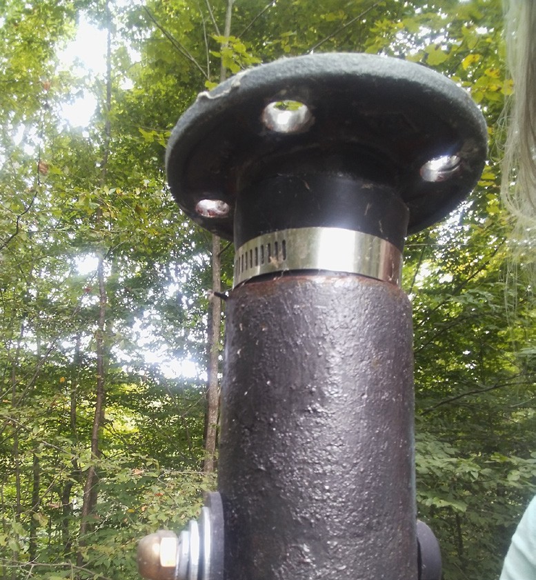
Flange, pipe, and rubber sleeve mounting assembly installed and secured with stabilizing bolt. Photo: A. Keuthan.
The generator needed a high surface on which to mount it. There happened to be an old deer-skinning hoist on a made-over swing set frame – in the back yard that I had repurposed as a frame for bean trellises. I tied off a ladder to the high post, climbed to the next to top rung, removed the rope from the pulley and used a metal cutting wheel to cut off the rusty top and level (leveling is extremely important) the steel post. It was now 10 feet high.
There was still nothing to which I could attach the base of the generator, so I decided to connect a flange to a pipe with a slightly smaller diameter and secure it to the top of the metal post. The holes in the flange were positioned to match the holes in the generator base but they were unfortunately not large enough for the bolts. Instead of buying smaller diameter bolts, I decided to make the holes bigger – overkill. Reaming the holes into the iron flanges (2 of them – because I bought 2 wind generators) without a drill press nearly killed me, even with the special drill bit. The first flange repeatedly flew via the torque of a power drill from the deck railing, over the flowerbed, and landed at the feet of a slightly exasperated “Grandmother Beech” tree, her hollow “mouth” exclaiming in disbelief, “Seriously!” The same drill torque twisted my wrist in the process. I figured out I had to use 16 penny nails to hold the flange in place while drilling. I credit the pain in my wrist for that bit of genius (sarcasm).
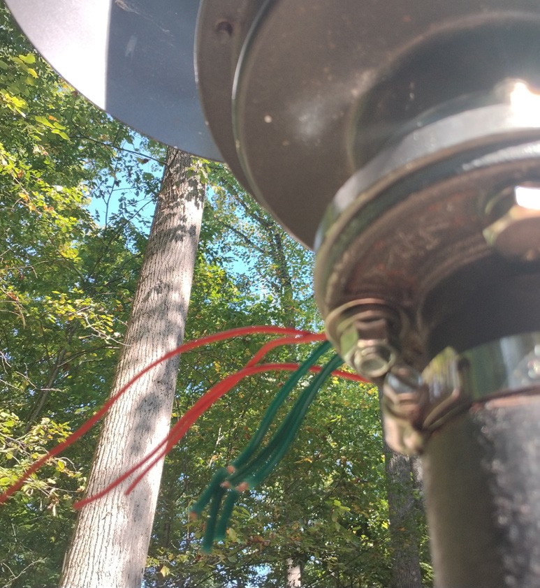
Red coated generator wires connect to slightly larger-gauge green coated copper wires that extend down a silicon topped flange and iron pipe and out of a hole in the post into a junction box. Note: photo shows the mounting flange and generator base without the silicon cushion, a repurposed jar lid opener, which was added later. Photo: A. Keuthan.
After resizing the 4 holes of both flanges to fit the generator base, I found thick rubber sleeves in the plumbing supply store and got two for each section of pipe. I slid one sleeve onto one end of pipe and the other on the other end, increasing the overall diameter of the pipe to fit snugly inside the 3 inch diameter steel post, then secured the sleeves with metal hose clamps and screwed an iron flange onto a threaded end of each pipe.
Hammering the pipe assembly into the post was a challenge. Once the bottom sleeve was hammered in, up to where I had placed the lower clamp, I had to remove the clamp to get the pipe the rest of the way into the post. By the time I got to the second sleeve at the top, flange end, the bottom sleeve had moved up pushing into it. Having the flange already attached helped for two reasons. First, I had to hammer the pipe out a little and rehammer a couple of times to keep the two sleeves from smashing together. Secondly, hammering might have damaged the threads of the pipe. As it was, I placed a short piece of 2×4 inch pine board on top of the flange to protect it from the blow of the hammer. Call me Sister of Thor.
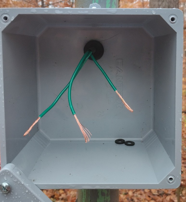
Wire bundle extends through a .” hole in the post and a second hole drilled into the back of the junction box, shown with rubber washer inside box and shrink wrap over wires. Photo: A. Keuthan
After the pipe was hammered in with the flange resting about an inch above the cut opening, I bored a hole through the heavy gage steel post and iron pipe – this took some patience. I then put a rubber grommet into the outer hole next to the bolthead and a rubber washer on the opposite side to cushion the stabilizing bolt from vibration caused by the spinning generator blades.
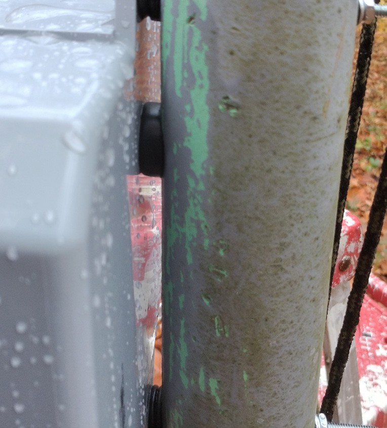
Junction box is shown attached to post using rubber bushings and washers for added protection from water, debris, and vibration. Photo: A. Keuthan
The next step was to attach the blades to the vertical axis of the generator. Even with clear instructions on how to achieve this, it was still a bear. Nothing wanted to align easily after attaching the blades to the top rod. I had to get serious with rod #2 and then lay the whole thing on its side and use my body weight to bend the steel blades inward, getting the last rod into the pre-drilled blade holes. This was all while constantly readjusting the second and first rows thinking it would help – it didn’t.
Another step the instructions failed to cover is the methods for safely lifting and securing the generator assembly onto the mounting surface and for connecting wires to it.
First, I bought a roll of wire in a slightly but not significantly larger gage than the three red wires protruding from the base of the generator. I drilled a hole into the post at about eye level and strung three green wires through the hole using a long piece of baling wire. I precut the green wires to be long enough to extend a few inches out of the hole, up through the post, and an extra few inches out of the top of the mounting surface. Next, I cut an X about an inch in diameter, through which three pairs of wires connected with screw-on caps can be pushed, into the center of a green silicon disk (a repurposed jar lid gripper) that acts as a cushion between the iron flange and the generator base. I also cut four small slits in the silicon disk for the bolts. I put the silicon disk, four bolts, washers, nuts, lock washers, and crescent wrench (to secure the bolts) into my pockets (a tool belt and pouch works even better). At this stage you will need a second ladder and possibly a bungee cord on which to rest and momentarily stabilize the bulky, awkward, heavy generator assembly once you haul it up the ladder. This will give you a second to catch your breath.
Now for the really fun part. First, put the silicon disk/jar lid gripper – lip down – over the iron flange and align the slits with the holes in the flange. Next, while holding your balance on the ladder (scaffolding would have been a plus), grip the axis just under the middle horizontal rod with one hand and hold the base of the generator with the other hand. This is tricky. You will notice how easily the axis turns on the base. The base wants to turn one way while the blades and axis turn the opposite way, giving the generator unit a rolling-off-the-cliff effect. This can be minimized by cutting a piece of thick pipe insulation and wedging it around the axis between the mounting base and the wider coil casing.
Now lift the whole thing upward and gently rest it atop the iron flange, careful to keep your grip on the axis so it does not fall or move too much, and doubly careful to keep your balance. I used the post to steady myself. Then, align the holes of the base with the slits in the silicon and the holes in the flange, being careful to keep the three red and three green wires on the exterior of the post, clear of the bolt holes and in a group to one side. Continue holding the generator firmly and get a bolt into one of the holes, from the bottom upward, then quickly screw the nut onto the bolt, snugly securing the base of the generator to the flange. Repeat for the remaining three bolts and take a coffee break. Better yet, have lunch.
After assembling, manually raising the generator, and carefully bolting it to a flange assembly secured to the top of a heavy-gauge steel post with a cemented base (as described in part 1 published in the online version of the Native Sun News), I realized one very significant thing: the total height is 14 feet. The surrounding trees, however, are tulip poplar, most of which are 60-75 feet high, as are the maple, beech, and oak. What I have is a windbreak that obstructs 75-90% of the wind flow, especially in warmer months when leaves are in abundance.
Another thing to consider is the probability of winter ice and snow build-up. In the Great Lakes states this is a given. More research is needed to address ice mitigation and maximize the wind current to electrical current ratio, while reducing risk to wildlife. Although my hope was to have extra power for backup energy needs, this project was mainly intended for me to gain experience for future projects. I still recommend this system for residential uses in less heavily wooded areas and places with more frequent and higher winds, like in the upper Midwest and plains states, coastal areas with low tree cover or grassy shrubby land cover. The helix kits available for purchase can produce up to 10,000 Watts or 10 kW. This one is only a 400 Watt magnetic levitation vertical helix wind powered generator, approximately 4 feet high by 2 feet in diameter, by Maglev. In part 1 of this series we discussed assembly of an in-ground steel post and iron flange mounting system. In this segment, I will explain the installation of the junction box and how to connect the generator wires to the wires that extend inside the junction box.
For the following steps, I recommend having a second person on a steady ladder to help you balance and hold the generator during this step. I also recommend doing this when there is little or no wind. I did not do either. Without a second person, bungee cords are helpful to momentarily secure the turbine. I bungeed my ladder to the main post from the start.
Connecting the First Wires
The next step requires wire cutters, a wire stripping tool, 4 carpenter’s pencils, a roll of electrical tape, a long flat screwdriver, a crescent wrench to tighten or loosen the bolts on the generator base, 3 twist-on wire end caps (yellow plastic with metal inside), 4 bolts about one inch longer than those in the mounting assembly, 4 nuts to fit those bolts, and a good supply of patience. With these items in a tool belt pouch, climb the ladder so you can easily view and work on the base of the generator.
First, strip the insulating cover about ¾ inch in length from the ends of the wires. Then, connect three pairs of wires, one red to one green, twisting the ends together in a clockwise direction. Screw one wire connector end cap onto each pair of connected wires, also in a clockwise direction. Tear off an 8 inch length of electrical tape and wrap it tightly in a spiral around the cap and at least a half inch of the red-green wire pair to keep the cap from slipping off the twisted wires. Repeat the process for the remaining wire pairs.
Now the connected wires must be moved to the center of the flange and down into the post. To do this, first loosen all the bolts and carefully remove 2 of the bolts at a time (any 2 will do). Temporarily replace those 2 bolts with slightly longer ones (about 1 inch longer). Place the longer bolts into the holes from underneath the iron flange and secure loosely with the nuts. Repeat this for the other 2 bolts.
Next, carefully lift the turbine base or, if doing this without help, carefully tilt it one side at a time and slip two of the flat carpenter’s pencils as spacers between the base of the turbine and the silicon covered mounting flange. Use a flat screwdriver to wedge the pencils under the generator. Make sure the pencils are apart on each side of the wire bundle and so they are not blocking the center where the wires will be pushed down into the post. Holding the main axis of the generator steady with one hand, tilt it up enough on one side to slide another carpenter’s pencil on top of one of the pencils there. You will need enough space to allow you to poke the capped wires, one connected red-green pair at a time, down into the center of the silicon disk and mounting flange. You will need about an inch of space to accomplish this, so if the temporary bolts are too short or too tight, either loosen them or remove 2 or 3 of them.
When the connected wire ends are positioned into the post, the base must be secured to the flange using the original bolts, removing one longer bolt and replacing it with the shorter bolt, one at a time, until all 4 bolts are secured with washers, lock washers and nuts, in that order. Tighten the nuts with a flat crescent wrench, the same size as the nut. The wires are now safe from moisture and debris. As an added layer of protection from the elements, squeeze some clear silicon caulking around the perimeter where the generator mounting base and the silicon-topped flange come together.
Now we are ready to install the junction box and grounding rod. You will need a waterproof junction box, a drill, 2 – 4 inch convex-head #10 bolts with rubber washers, metal washers, lock washers and #10 nuts or #10 wing nuts, an 8 foot grounding rod – usually ½” or .” in diameter – and a sledge hammer with which to hammer it 7 feet into the ground.
You will need to drill a .’ to ¾” hole in the back of the junction box, lining the hole up with the small bolt holes on the exterior of the box. The long green wires that extend from the generator at the top will come through this hole from the hole in the side of the post. I recommend pre-drilling the hole in the junction box and then measuring and drilling the large and small holes in the steel posts before stringing the green wires and prior to mounting the generator to avoid damaging wires while drilling. The two smaller holes will go at a perpendicular angle through both sides of the post, while the larger hole will only go through the side of the post where the junction box is to be attached. After the green wires are strung through the post and the mounting of the generator was completed, I shrouded the three green wires coming out of the post snugly together inside a shrink wrap tube. I then strung a rubber bushing, smaller diameter first, over the wires and positioned it into the hole to protect the wiring before stringing them into the junction box.
I used smaller bushings as spacers behind the connecting tabs of the junction box and then ran the #10 bolts through the tabs, the smaller bushing, and both sides of the post. The bolts are secured with a rubber washer, a metal washer, a lock washer and finally a #10 nut.
To prepare for the next steps, you will need a 6’ step ladder, the grounding rod, a bucket of water, a claw hammer, and a sledge hammer. First locate a spot near the base of the post away from any poured concrete and out of the path of where people walk. Use the claw side of the claw hammer to dig a hole into the ground several inches deep. I would use a pick axe if the ground is extremely rocky. Now pour the bucket of water into the hole, a third at a time, until it seeps into the hole. Place an end of the grounding rod into the hole and twist and push, using your weight to work it into the ground. If it hits a stone, climb the ladder and use a hammer to drive it in further. When it is half way into the ground, move the ladder away from the rod and use a sledge hammer to drive the rod the rest of the way into the ground. Leave 8”-12” of grounding rod exposed so it is easy to install and maintain the grounding wire.
In the next segment we will attach the wires inside the junction box to the charge controller that came with the generator kit, install the solid 10 gauge copper ground wire, lay out the conduit and fittings and begin stringing wire to the general location of the battery pack housing. We are just getting to the fun part, so I’ll keep all of you posted on the process. Until next week!
To get more detailed photos of materials needed and information contact: kestreldancing@gmail.com
The post Avian-friendly wind power first appeared on Native Sun News Today.
Tags: Environment

